
Getting started
Marionnet was designed to be used straight away, with no prior training. Indeed, from 2007
to 2024, at Université Paris 13, no lab session was ever spent on learning the software (at
least in the courses of Marionnet’s authors, that is, about a thousand students). Students
started directly with a TCP/IP networking lab. They went a little slower in the first session,
then discovered the rest of the features as the following sessions went by. This page therefore
only describes how to build a first network: three machines connected to a switch, able to
reach one another with the ping command.
The first network
-
Create a new project from the Project › New menu. A dialog window then asks you for the name of the file (with the
.marextension) that will hold the project, in other words your virtual lab room. Once the project is created, the component palette, on the left-hand side of the window, becomes active. -
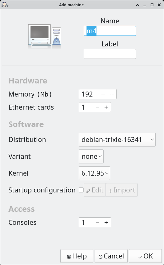
Add three machines: in the palette, click on the machine icon, then on Add. The dialog window that opens suggests a name (
m1, thenm2andm3), along with hardware and software settings that are fine as they are for this first network. Then add a switch the same way. -
Connect each machine to the switch with a straight cable, which you also add from the palette, giving its two ends in the dialog window. Note that you do not draw the network: you simply declare the components it is made of, and Marionnet keeps the map of the network, in the middle of the window, up to date.
-
In the Interfaces tab, below the map of the network, assign an address to each machine by double-clicking on the IPv4 address cell: for instance
10.0.0.1/24form1,10.0.0.2/24form2and10.0.0.3/24form3. Each machine applies its address when it starts. -
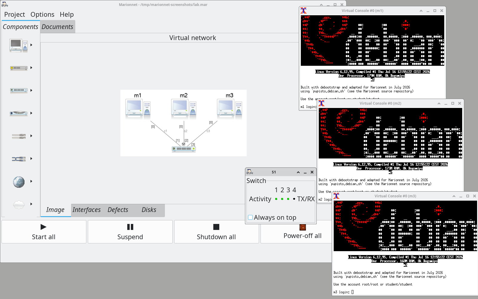
Start the network with the Start all button, at the bottom of the window. Each machine then opens a terminal, where you log in, as on any Unix system, with a user name and a password: by default, the
rootaccount has the passwordroot(admittedly, this is not advisable, but it is only a virtual machine after all!). You can then test the link from the terminal ofm1:ping 10.0.0.2 -
Save the project from the Project › Save menu. The file keeps not only the definition of the network but also the content of each machine’s disk (only what has changed since the original image, which keeps the file small): when the project is opened again, the machines will therefore find their files and their configuration as they left them.
What comes next
Each icon of the palette opens a menu that offers always the same actions: add, modify or remove a component and, for a device, start or stop it. The other features do not need to be learnt beforehand: they are discovered as the sessions go by, as the exercises require them. For instance:
- hot reconfiguration: as in reality, a cable can be unplugged and plugged in elsewhere without shutting the machines down, and a cable of the wrong kind (straight instead of crossover, or the other way round) behaves as if it were not there;
- the simulation of faulty links (Defects tab): frames lost, duplicated or delayed;
- the history of the states of each machine (Disks tab);
- access to the real network, through three components (Gateway, NAT bridge and LAN bridge);
- the exam mode (
--examoption), which records what each student did during the session.
To learn more
The Features and Screenshots pages of the site describe each component in more detail and show the interface as it is today.